

We want to keep you in the loop! Our website is currently undergoing some exciting enhancements to provide you with an even better online experience.
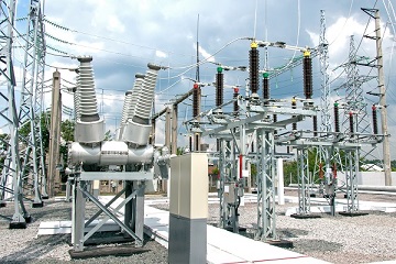
The scope of work concerned a Medium Voltage/High Voltage 100MVA substation located at the end of a relatively long radial transmission line. A load increase was forecasted for the next years and it was planned to replace the actual capacitor bank by a 50MVAR unit to provide the additional power without a severe voltage dip.
The first step of the study consisted in modelling the substation using EMTP. Capacitor banks, current-limiting reactors and circuit breakers are modeled using ideal devices. In order to get the appropriate level of details required by capacitor bank switching analysis, bus work inductances are derived from typical values found in IEEE C37.012-2005. Surge arresters are modeled using the IEEE arrester model for fast front surge. Incoming transmission lines are modeled using a frequency-dependent model built using the power frequency impedance data and the EMTP Line Rebuild tool. The upstream network model is validated by comparing the load-flow results calculated by EMTP with the results provided by the client.
Four scenarios are analyzed using EMTP:
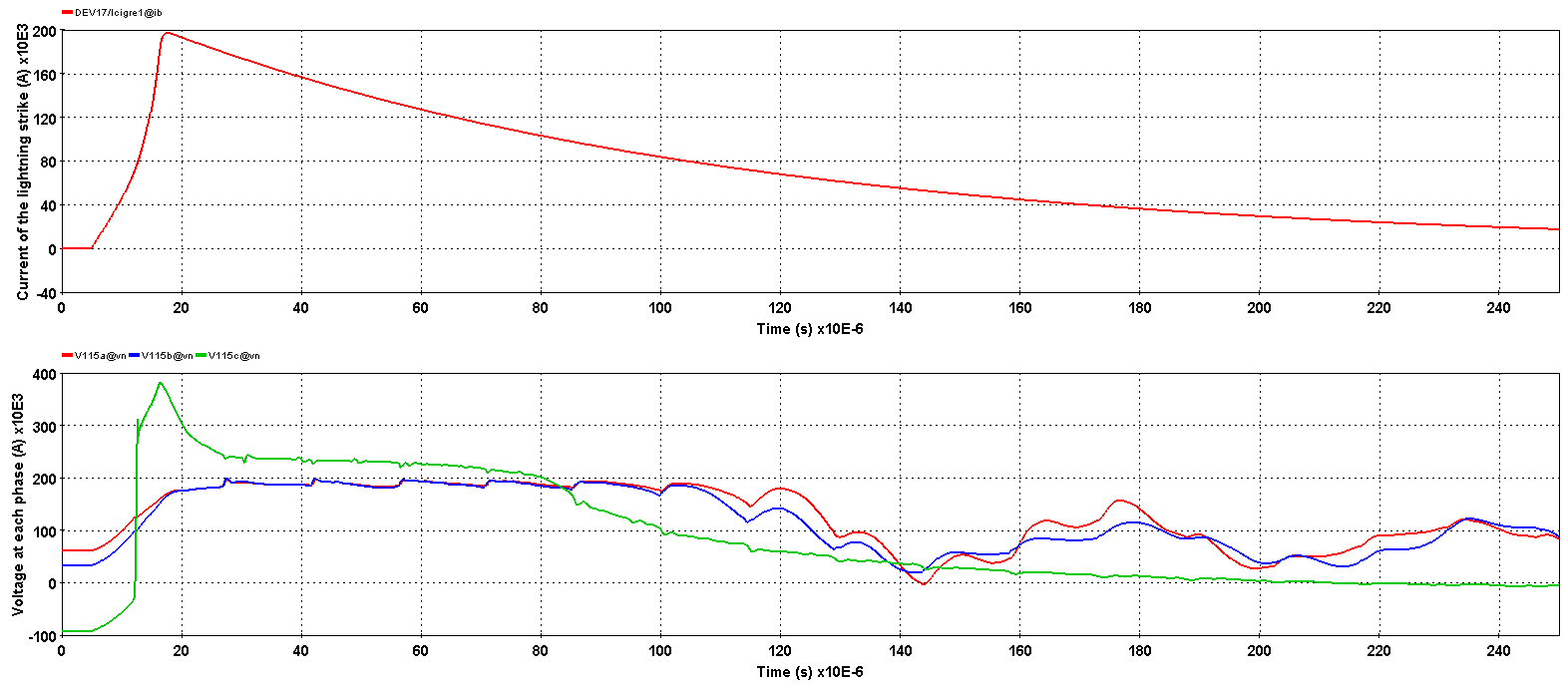
Simulation shows that the maximum switching overvoltage is kept below the limits and the system should be safe from the overvoltages originated from the switching of the capacitor bank. If a fault occurs between the capacitor bank and the current-limiting reactor, the TRV analysis confirms that the circuit breaker is able to open without any problem.
In the case of 3-phase fault on the 115kV bus, there was a small hazard of circuit breaker damage. The product of the inrush current peak and transient inrush current frequency was slightly higher the IEEE limit, which is an unnecessarily restrictive criterion.
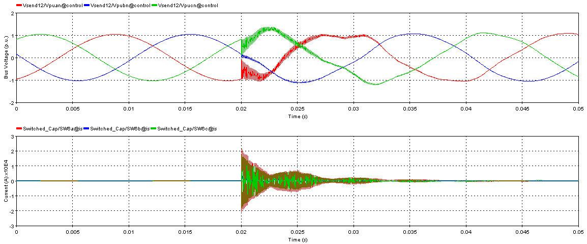
Overvoltages (top) and in inrush current (bottom) during the capacitor bank switching