

We want to keep you in the loop! Our website is currently undergoing some exciting enhancements to provide you with an even better online experience.
The main objective of work is to calculate eddy current losses in the solid iron body of the rotor for one claw pole generator, which is connected to rectifier (Fig. 1). For this purpose, a 3D time transient analysis in JMAG is performed to analyze 3D eddy currents losses in the rotor. End winding is precisely modeled to consider eddy currents in end regions of the rotor. This study shows how JMAG can save a lot of time for one complicated 3D model with eddy currents consideration.
The first part of the study is to model precisely the claw pole generator with real end winding configuration and rotor solid iron body. Skin mesh of JMAG is used in the rotor to model the skin effect. Extruded mesh is applied for meshing to decrease number of elements and reduce simulation time. Second step is to run the model and evaluate the results. In order to read rotor eddy current losses at steady state condition we need to simulate 9 electrical periods, which is long time for 3D simulation. We use time reduction technique in JMAG to decrease simulation time almost 80 %.
Two simulations are analyzed using JMAG:
Simulation shows eddy currents distribution and eddy current losses distribution in the rotor of claw pole generator (Fig. 2).
The transient time is considerably decreased, which help to save time especially for large model and parametric calculations and optimization (Fig. 3). The accuracy of all magnetic and results.
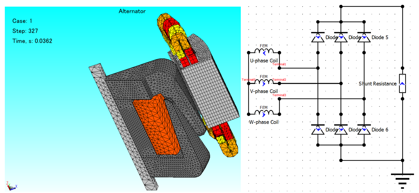
Fig. 1 Claw pole generator model with mesh in JMAG (left) and used electric circuit in JMAG (right)
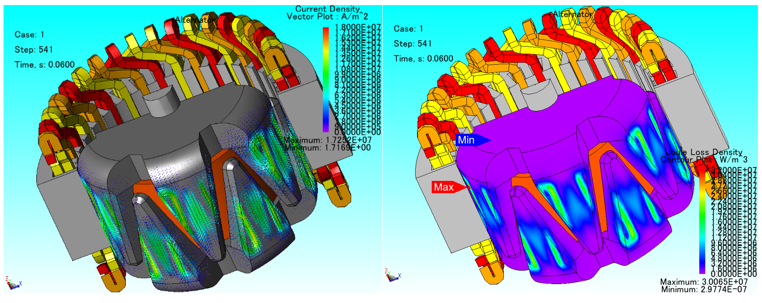
Fig. 2 Eddy currents distribution in the solid iron rotor (left) and eddy current losses distribution in the solid iron rotor (right)
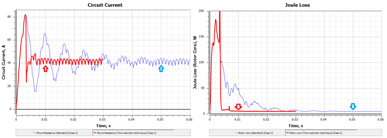
Fig. 3 Circuit current versus time (left) and eddy current losses versus time in the solid iron rotor (right) – Blue lines are without time reduction techniques in JMAG and red lines with time reduction technique in JMAG